2008-12-03 update: One of the boards I got finally ran out of batteries. As I expected, it was the microcontroller’s battery, not the display batteries that went completely dead first.
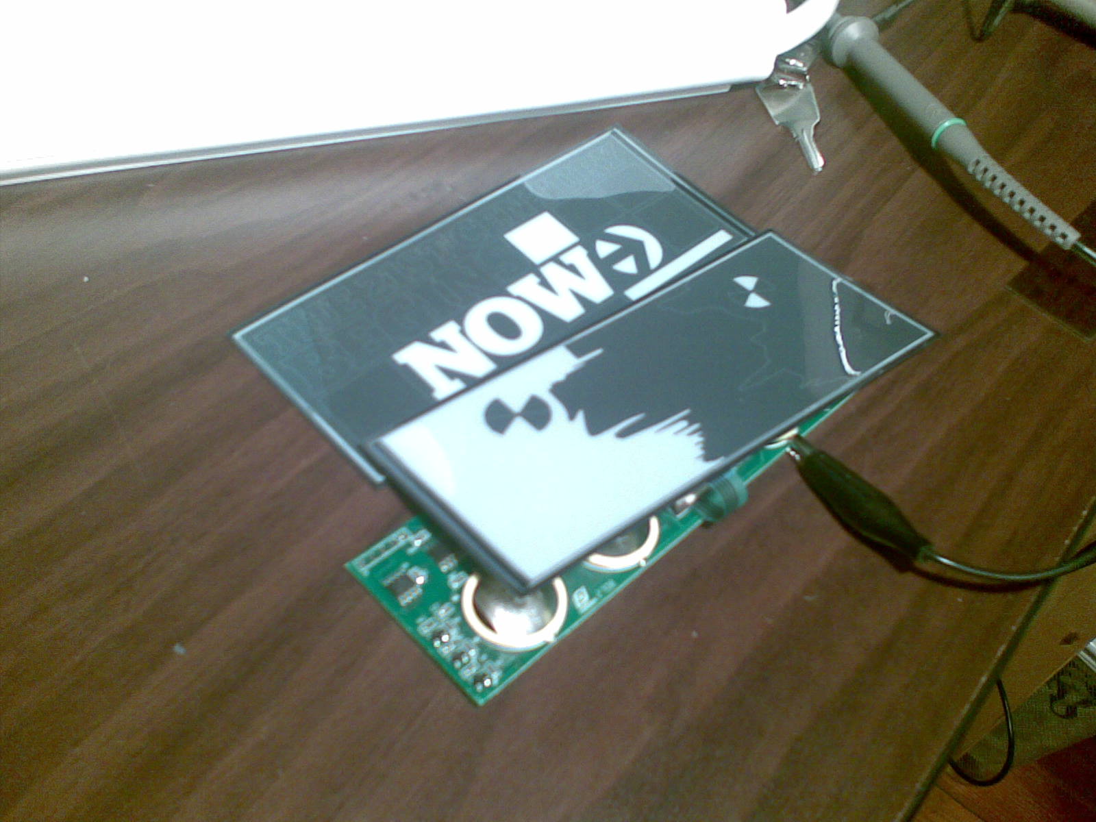
Esquire magazine’s October 2008 cover has 2 E-Ink segmented displays on them. One on the front (“The 21st Century Begins Now”) and one on the back (part of an ad for a car). The front display has 11 segments and the back has 3. The layout with the individual segments is shown below in the SVG documents.
SVG segment overview
Below are SVG images of the displays. Each segment on the display is turned into an SVG path. I originally created this to come up with a cool mask to put over the display in order to have it display something more useful than the ads. So far, my best idea has been to put a simple mask over it that turn the big blocks into icons and represent some infrequently-updating status with it (weather, network status, disk usage, etc.)


Here is a first attempt at making the car ad display more useful. Each of the segments now represents some basic emotion or health.

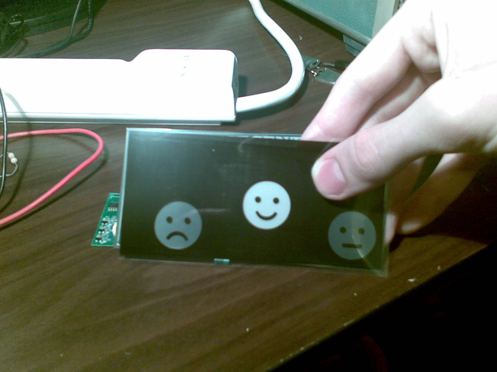
This was drawn in Inkscape and printed on transparency on a laser printer.
Electronics hacking
I started by looking at the various resources online, such as flickr user just_mike’s photos, which includes a copy of what Make user maushammer posted to the above Make post. This has been copied here below:
ISP Pinout:
Pin 1: VDD
Pin 2: GND
Pin 3: VPP
Pin 4: pin 6 (ICSPCLK)
Pin 5: pin 7 (ICSPDAT)
PIC 12F629
Pin 1: VDD [3 volts]
Pin 2: not used
Pin 3: not used
Pin 4: VPP/MCLR and S1
Pin 5: goes to R5/Q3/R6
Pin 6: goes to R3/Q2/R4
Pin 7: goes to R1/Q1/R2
Pin 8: GND
S1 (the unpopulated switch) is connected to pin 4, which is a reset pin… but it can also be programmed as an input. It acts like a reset, though.
Battery 6 powers the microcontroller only. (3 volts)
Batteries 1-5 generate 14.86 volts - available at C3
… I wonder which power supply will run out – battery 6, or batteries 1-5.
Q1-3, R1-6 convert 0-3 volts from the CPU to 0-15 volts for the high-voltage drivers (U2 & U3).
U2 & U3: HEF4094BT - 8 stage shift-and-store bus register
Pin 3 is the clock - 30 Hz - it’s slow because the Q1-3 voltage translator is slow.
Pin 2 is the data - varies depending which segments need to be lit
Pin 1 is the strobe - 2.7 Hz - allows all the outputs to switch simultaneously.
oscilloscope timing analysis
See also: Flickr copy for comments
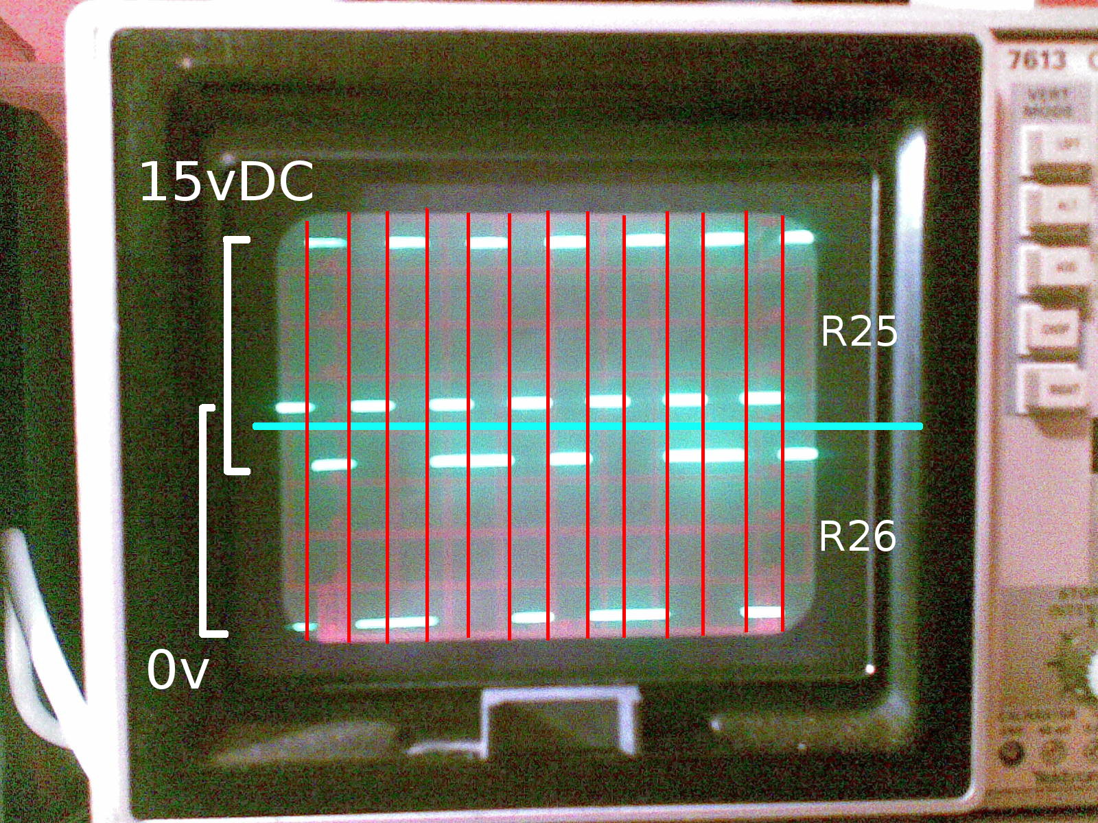
I hooked up 2 of the 4 pins that go to the car ad display to my oscilloscope. They are designated based on the resistors that are connected to them (R25 and R26). R27 and R28 seem to have the same pattern as R26, so those represent the individual segments. R25 seems to affect them all, as when it goes high (to +15vDC), one of the the display segments goes white.
It seems as though the output pins switch from +15vDC@19mA to 0vDC (this is with the display connected and active). The display changes when the voltage is different between the common R25 and the segments (R26, R27, R28). If the polarity is reversed between the common and the segment, it will toggle the element’s color.